Contrast artifacts in your microscope images occur when optical path differences, varying refractive indices, and thickness inconsistencies disrupt light waves. These distortions create halos around structures and misleading brightness variations. Misalignment between condenser and objective lenses worsens these effects, while digital sensor limitations struggle to capture the full dynamic range. Proper specimen preparation and digital correction techniques can considerably reduce these unwanted visual elements. Understanding these factors will transform your microscopy results.
Origins of Optical Path Differences in Phase Contrast
When light passes through biological specimens, it encounters materials with varying refractive indices that create optical path differences (OPD).
You’ll notice these differences arise from two critical factors: specimen thickness and refractive index difference between the specimen and surrounding medium. The mathematical relationship OPD = t(n(s) – n(m)) quantifies this phenomenon, where even minor variations greatly impact your phase contrast microscope images.
These OPDs generate phase shifts that conventional light microscopy can’t detect.
Phase shifts arising from optical path differences remain invisible under standard light microscopy conditions, limiting conventional imaging capabilities.
Phase contrast imaging converts these shifts into amplitude differences, making previously invisible structures visible. However, this conversion isn’t perfect—the phase shift differences at specimen boundaries often create unwanted artifacts like halos that can complicate your interpretation.
Understanding these fundamental principles helps you recognize when contrast variations represent actual structures versus imaging artifacts.
Halo Effect Formation at Specimen Boundaries
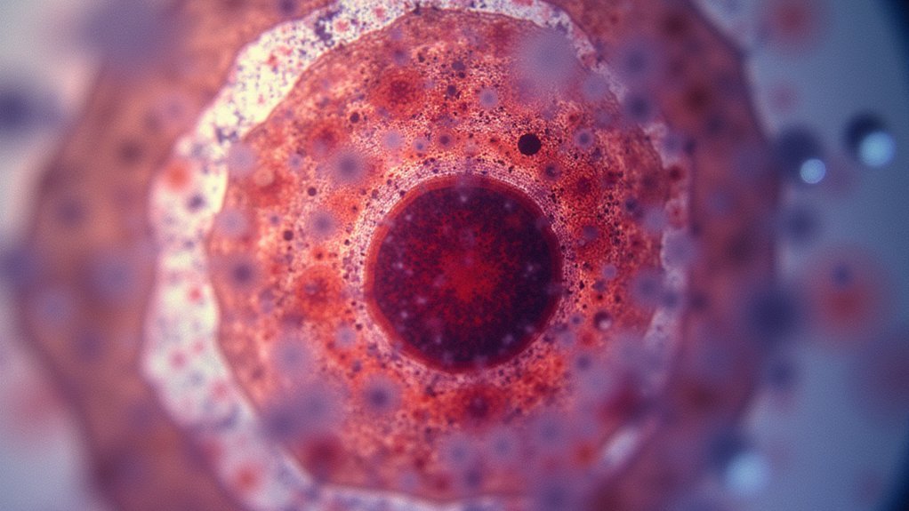
As you examine specimens under phase contrast microscopy, you’ll inevitably encounter the characteristic halo artifact—bright, glowing rings that surround cellular structures and organism boundaries.
These halos form when light diffracts at interfaces between materials with different refractive indices, creating artificial brightness that can obscure essential details.
The intensity of the halo effect varies with specimen thickness and your microscope’s optical setup, particularly the numerical aperture of your objectives.
Misalignment of optical components like phase rings often exacerbates these artifacts, distorting light paths and enhancing unwanted halos.
To minimize these boundary distortions, you might consider switching to differential interference contrast techniques, which provide sharper edge definition by reducing the impact of light diffraction at specimen boundaries, allowing you to observe structural details with greater accuracy.
Impact of Condenser-Objective Misalignment
Proper alignment between your condenser and objective represents the cornerstone of artifact-free microscopy. When misalignment occurs, you’ll notice uneven illumination across your specimen, creating contrast artifacts that obscure fine structural details.
Condenser-objective misalignment disrupts the light paths traveling through your specimen. This inconsistency affects both phase and amplitude of transmitted light, potentially leading you to misinterpret what you’re seeing.
Misaligned optics create phantom structures by disrupting light waves—what you observe might be artifice, not reality.
When your condenser’s numerical aperture doesn’t match your objective’s, you’ll experience reduced resolution and contrast, making critical structures harder to distinguish.
Watch for telltale signs like halos or shadows appearing in your images—these indicate alignment problems requiring correction. Addressing misalignment is essential for maximizing contrast while minimizing artifacts, ensuring you achieve accurate visual representation of your microscopic specimens rather than viewing technical aberrations.
Thickness Variations and Refractive Index Gradients
Specimen thickness variations create some of the most persistent artifacts you’ll encounter in microscopic imaging. When your sample’s thickness isn’t uniform, light scatters and refracts differently across regions, making some areas appear lighter or darker than they should. This inconsistency creates contrast artifacts that can mask important specimen detail.
Refractive index gradients compound this problem. As light waves travel through varying specimen compositions, they bend differently, creating optical path differences that generate phase shifts. In phase contrast microscopy, these variations produce characteristic halos around edges where small refractive index differences exist between the specimen and surrounding medium.
For accurate imaging, you’ll need to control specimen preparation carefully. Consistent thickness and minimal refractive index gradients guarantee more reliable contrast and fewer misleading visual effects that could compromise your interpretation of microscopic structures.
Digital Sensor Limitations in Capturing Dynamic Range
While optical resolution often receives the most attention in microscopy discussions, the digital sensor’s limited dynamic range presents equally significant challenges for accurate imaging. Most microscopy digital sensors offer only 12 to 14 bits of dynamic range, which can’t adequately capture high-contrast specimens.
You’ll notice contrast artifacts appearing when subtle intensity variations become indistinguishable due to the sensor’s limitations. In low-light conditions, sensor noise becomes particularly problematic, introducing unwanted artifacts that degrade image quality.
Additionally, quantization error creates visible steps in gradually changing brightness levels, obscuring fine details that might be critical for your analysis. To minimize these issues, you’ll need proper calibration and careful adjustment of exposure settings.
Polarization-Induced Distortions in Image Formation
When polarized light interacts with birefringent specimens, complex distortions emerge that can greatly alter your microscope’s image accuracy. You’ll notice contrast artifacts develop when using crossed polarizers with samples exhibiting non-uniform birefringence, potentially misleading your interpretation of structural details.
| Effect | Cause | Consequence |
|---|---|---|
| Intensity variations | Specimen orientation | Hidden crucial features |
| Shadow formation | Polarizer misalignment | Distorted morphology |
| False structures | Optical path differences | Misinterpreted details |
These distortions occur because refractive indices vary throughout birefringent specimens, creating phase shifts that appear as structural elements in your image formation process. The positioning of anisotropic materials relative to your polarized light source greatly impacts visibility—potentially obscuring essential information you’re seeking to observe and analyze.
Challenges With Specimen Preparation and Mounting Media
Proper specimen preparation forms the foundation of accurate microscopic imaging, yet numerous technical pitfalls can undermine your results before you even adjust your first focusing knob. Inadequate fixation or staining creates refractive index variations that introduce unwanted contrast artifacts in your images.
Your choice of mounting media critically affects image quality. When the refractive indices between your specimen and mounting medium don’t match, optical distortions appear and clarity diminishes.
Thick specimens or uneven sectioning cause light scattering and diffraction issues, degrading detail and increasing background noise.
Watch for air bubbles or debris in your mounting media—these common culprits cast shadows that compromise accurate visualization.
Similarly, uneven application of chemical dyes leads to inconsistent absorption patterns, creating artifacts that obscure the true morphological features you’re trying to document.
Advanced Computational Methods for Artifact Suppression
Once your specimen is prepared, digital processing takes artifact management to new levels. In optical microscopy, you’ll find Fast Fourier Transform (FFT) techniques particularly effective at identifying and filtering periodic noise patterns that compromise image clarity. Median filtering reduces salt-and-pepper noise while preserving critical edge details in your specimens.
For uneven light distribution issues, several powerful solutions exist. The BioVoxxel Pseudoflatfield correction normalizes background illumination variations across different specimen regions. When working with multiple images, CIDRE estimates flatfield correction by analyzing your dataset collectively, minimizing illumination artifacts.
For image stacks, BaSiC effectively corrects background variations, ensuring consistency throughout your experiments. These advanced computational methods for artifact suppression represent essential tools in modern microscopy, transforming problematic raw data into publication-quality images that accurately represent your specimens.
Frequently Asked Questions
Why Is the Contrast of a Microscope Image Important?
Contrast in microscope images is important because you’ll need it to distinguish cellular components clearly. Without sufficient contrast, you can’t identify vital details, leading to potential misinterpretation of biological structures and processes.
What Is the Function of the Contrast Microscope?
The contrast microscope helps you see transparent or low-contrast specimens by converting light phase differences into visible intensity differences. You’ll observe living cells and thin specimens clearly without staining, revealing otherwise invisible details.
What Increases Contrast on a Microscope?
You can increase contrast on a microscope by applying stains, using phase contrast techniques, adjusting the aperture settings, employing DIC methods, or utilizing darkfield microscopy to enhance visibility of specimen structures.
Why Do Images Appear Inverted When Viewed Under the Microscope as Compared to the Ones Viewed From the Side?
Images appear inverted because microscope lenses bend light rays in a way that flips your specimen. This optical property creates a real, inverted image at the focal point—it’s simply how convex lenses work.
In Summary
You’ll encounter contrast artifacts in microscopy due to optical path differences, boundary halos, and misalignment issues. These distortions arise from thickness variations, refractive index changes, and digital sensor limitations. Polarization effects and improper mounting further complicate imaging. While challenging, you can minimize these artifacts through proper technique and advanced computational methods, ultimately improving the accuracy and reliability of your microscopic observations.
Leave a Reply