
To install your stage controller, start by unpacking all components and inspecting for damage. Mount the controller at least 100mm from heat sources in a well-ventilated area. Connect silicone hoses of equal length and secure with quality clamps. Wire the toggle switch and 1A fuse to the ignition source. Program your desired boost levels in the memory positions. Test all connections for leaks before operation. Proper installation guarantees peak performance for precise boost control.
Preparing Your Workspace for Controller Installation

A clean, organized workspace isn’t just about appearances—it’s essential for a successful stage controller installation. Before beginning, gather all required components: silicone hoses, clamps, toggle switch, and a 1A fuse. Having everything at hand will streamline your installation process considerably.
Select a well-ventilated area away from direct heat sources. Remember, your controller should be mounted at least 100mm from any heat-generating equipment. Work on a clean bench to prevent contamination and keep all parts visible.
Keep a magnetic tray or small container nearby to safely store bolts, screws, and other small components you’ll remove during installation. This simple precaution prevents the frustration of searching for dropped parts and guarantees nothing important goes missing during your setup.
Required Tools and Components Checklist
Before you begin installing your dual stage boost controller, gather all essential equipment including pressure testing tools and appropriate fittings.
You’ll need proper silicone hoses with the correct size and pressure rating, along with clamps to secure all plumbing connections and prevent leaks.
Don’t forget the electrical components such as a toggle switch and 1A fuse for safely wiring the controller to an ignition source.
Essential Installation Equipment
Proper installation of your stage controller requires several critical components and tools before you begin.
You’ll need appropriately sized silicone hoses that meet the pressure rating specifications for the TS-0105-100X dual stage boost controller. Secure all connections with quality clamps to prevent pressure leaks during operation.
For electrical integration, prepare a toggle switch and a 1A fuse to connect with your ignition source wire. Confirm you have access to pressure source and wastegate actuator ports, along with the DSBC Tee piece for proper wastegate actuator connection.
Maintain a clean workspace for all modifications.
Before reinstallation, verify that all internal air passages are free from debris that could compromise performance.
Having these essential components ready will guarantee a smooth installation process and maximum controller function.
Hoses and Clamps
Selecting the right hoses and clamps forms the foundation of a reliable stage controller installation. You’ll need silicone hoses specifically sized and rated for your system’s pressure requirements.
Don’t compromise on quality here—proper materials prevent failures under pressure.
Cut all hoses to equal lengths to guarantee consistent pressure distribution throughout your setup. This simple step prevents performance irregularities that could affect your controller’s function.
Secure every connection with high-quality clamps that won’t loosen during operation.
Before final installation, inspect all hoses for splits, cracks, or damage that could lead to leaks or system failure.
Route your hoses strategically, keeping them away from heat sources and moving components that could cause wear over time.
Proper routing extends the life of your installation and maintains peak performance.
Wiring Necessities
When gathering your wiring supplies, you’ll need to verify you have all essential components before starting the installation process. A toggle switch is vital for controlling power flow to your stage controller, while a 1A inline fuse provides necessary circuit protection when connected to your ignition source.
Select appropriate gauge wiring with sufficient length to reach from your controller to the 12VDC power source. Don’t skimp on connectors—high-quality options guarantee reliable electrical conductivity and resist corrosion over time.
While preparing your wiring setup, keep your silicone hoses organized as well. These must have the correct diameter and pressure rating for connecting the controller to the wastegate actuator.
Finally, secure everything with proper clamps to prevent disconnections during operation, especially under high-boost conditions.
Unpacking and Inspecting Your Stage Controller
Begin your Stage Controller installation by carefully removing it from the packaging and thoroughly inspecting for any physical damage or defects.
Check that your package contains all required components, including the dual stage boost controller and necessary fittings, and verify the product number matches TS-0105-100X.
Look for any signs of wear or contamination on the controller parts to guarantee peak performance before proceeding with the setup process.
Initial Package Verification
Upon receiving your stage controller, carefully examine the packaging to validate the product number TS-0105-100X matches what you ordered. Check the entire package for shipping damage that might affect functionality.
| Component | Verification Step |
|---|---|
| Product Number | Match TS-0105-100X with label |
| Package Condition | Inspect for external damage |
| Components | Confirm all parts present (DSBC Tee, wiring) |
| Documentation | Verify version V1.00 Rev B |
| Product Condition | Look for signs of previous use |
Before installation, remove all components and cross-reference them with the included inventory list. Ascertain documentation matches the current version for accurate troubleshooting guidance. If you notice any discrepancies or damage, contact customer support immediately before attempting installation to avoid potential performance issues.
Pre-Installation Component Check
Now that you’ve verified your package externally, it’s time to properly unpack and examine each component of your Stage Controller.
Open the package carefully and remove all parts, ensuring the dual stage boost controller and installation hardware are intact.
Inspect the controller for any dents or scratches that might affect performance. Confirm that the product number TS-0105-100X matches your documentation and you have the correct V1.00 Rev B version for reference.
Check all included hoses for proper size and pressure rating compatibility with your specific setup. Don’t overlook this essential step as incompatible hoses can lead to installation problems.
Before proceeding, review the installation guidelines to familiarize yourself with required tools and components you’ll need for a successful installation.
Mounting the Controller to Your Microscope System
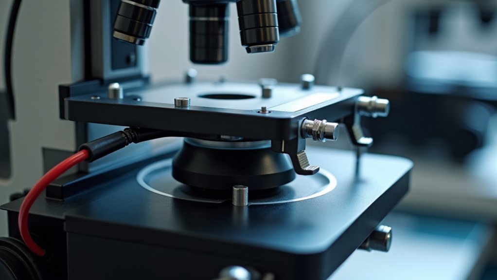
Proper mounting of your stage controller is essential for ideal performance and longevity. Position the controller at least 100mm away from any heat sources to prevent overheating and guarantee reliable operation.
Secure all connections with appropriate clamps to eliminate leaks that could compromise system performance. When connecting the electrical components, ground one wire and connect the other to a 12VDC source, installing a toggle switch and 1A fuse inline with the ignition wire for protection and easy control.
| Mounting Component | Distance Requirement | Purpose |
|---|---|---|
| Controller Unit | 100mm from heat sources | Prevent overheating |
| Silicone Hoses | Sized to match setup | Secure connection |
| Electrical Wiring | Extended as needed | Proper functionality |
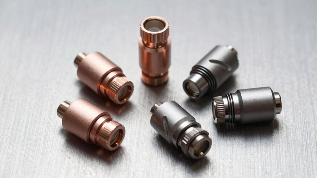
Connecting Power and Communication Cables
After securing the physical mounting of your stage controller, the next step involves the electrical connections that will bring your system to life.
Physical mounting is only the beginning. Next comes the critical electrical work that breathes life into your controller system.
You’ll need to extend the wiring to connect your controller to a 12VDC power source for peak performance. Ground one wire to a suitable chassis point to establish a reliable electrical connection.
For convenient power control, install a toggle switch in-line with the ignition source wire. Make sure all connections are secure and properly insulated to prevent shorts or disconnections during operation.
The complete wiring specifications can be found in the product manual (Document version: V1.00 Rev B), which provides detailed diagrams for power and communication connections.
Following these guidelines will guarantee your stage controller functions reliably and efficiently.
Calibrating the Stage Movement Parameters
Calibrating your stage controller requires careful attention to detail for peak performance. Before you begin, verify the system is cool and remove any factory control solenoids that might interfere with the calibration process.
Take advantage of the dual stage controller’s ability to select between two ramp rates, giving you precise control tailored to your performance requirements. Connect all hoses to the controller and wastegate actuator using equal lengths, and secure them firmly to maintain consistent pressure readings.
Make final adjustments only after verifying that no components are affecting the pressure source and actuator connections.
Maintain top performance by routinely inspecting for leaks and clearing any blockages in the controller’s internal air passages, which could compromise your calibration settings.
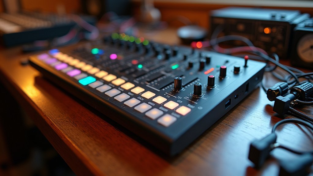
Setting Up Position Memory Functions
You’ll need to power on your stage controller and navigate to the memory settings in the user interface to configure position memory functions.
Store your favorite boost settings by pressing the designated save button after setting specific levels for each memory position.
You can quickly access these saved profiles during operation by simply toggling through the memory positions using the controller’s switch or interface button.
Memory Position Configuration
Three simple steps allow you to save your preferred boost settings for quick access during different driving conditions.
First, power on your dual stage boost controller and set the desired boost levels for each stage according to your performance needs.
Next, press and hold the memory button until the LED indicator flashes, signaling that your current settings are being stored. Release the button once the LED stabilizes, confirming successful storage.
To create multiple profiles, simply repeat this process for each memory position you want to configure. Different positions can accommodate various driving scenarios, from daily commuting to track days.
Once configured, verify your memory positions by switching between them to guarantee the boost levels match your saved settings.
Save Favorite Settings
With your memory positions configured, the next step is to organize your favorite settings for convenient retrieval.
Navigate to the position memory function on your dual stage boost controller’s interface when you’re ready to save your preferences.
First, adjust your controller to achieve your desired boost setting. Once you’re satisfied with the configuration, press the memory save button to store it.
You can create multiple profiles by assigning each boost setting to a unique position in the system.
For quick access later, follow the recall instructions detailed in your product manual.
Remember to periodically review and update your saved settings whenever you modify your vehicle’s boost system. This guarantees your controller maintains peak performance as your tuning requirements evolve.
Programming Custom Movement Sequences

Creating personalized movement sequences releases the full potential of your stage controller. Connect your controller to compatible software that supports parameter input before you begin programming.
Use the dual-stage boost controller’s two ramp rates to craft unique acceleration profiles. You’ll want to adjust how quickly boost increases during different operational stages.
The art of boost control lies in mastering ramp rates, creating a symphony of acceleration tailored to each phase of operation.
Take advantage of the wider adjustment range available for low spring base pressures to optimize performance across various load conditions.
Always test your programmed sequences in a controlled environment first. Monitor your vehicle’s performance feedback and make adjustments accordingly.
Keep detailed records of each sequence and its results – this documentation will prove invaluable when you’re fine-tuning your boost control strategy in the future.
Testing Precision and Accuracy of Movements
Precision testing represents a critical step in validating your stage controller’s performance.
Begin by checking all connection ports for blockages or contamination that could affect movement accuracy. Verify hoses connected to the controller are equal in length and tightly secured to prevent discrepancies in operational readings.
Conduct an extensive pressure test on the actuator system to confirm responsiveness and identify potential leaks compromising accuracy.
When adjusting settings, make gradual changes while monitoring readings to verify the controller accurately reflects your desired movement parameters.
Regularly inspect your stage controller for debris accumulation in internal passages.
Even minor blockages can cause erratic behavior and imprecise adjustments. Maintaining clean components guarantees consistent performance and extends the lifespan of your precision movement system.
Troubleshooting Common Installation Issues

Despite the most careful setup, installation challenges can still arise with your stage controller. First, verify the controller’s arrow points correctly toward the actuator to guarantee proper pressure regulation communication. This simple orientation mistake often causes erratic performance.
Next, examine all hoses for splits, cracks, or loose connections that might cause pressure loss or inaccurate readings. Remove any blockages or contamination within the controller that could impede proper function and flow.
Ascertain no additional components exist between the pressure source and actuator, as these can interfere with control precision.
Finally, conduct a pressure test on the actuator to identify potential leaks and confirm proper operation.
Addressing these common issues promptly will save you troubleshooting time and guarantee your stage controller functions efficiently during performances.
Frequently Asked Questions
How to Install a Dual Stage Boost Controller?
To install a dual stage boost controller, you’ll need to cool your engine, locate pressure ports, connect silicone hoses with proper tees, wire to 12VDC with a switch, and test all connections before adjusting boost settings.
What Does a Dual Stage Boost Controller Do?
A dual stage boost controller lets you fine-tune your engine’s performance using two separate ramp rates. You’ll get more precise boost control, prevent boost spikes, and optimize power while maintaining reliability in your turbocharged vehicle.
In Summary
You’ve now successfully installed your stage controller and learned how to program custom movements. With proper calibration, your system’s ready for precise research tasks. If you’re experiencing any issues, refer to the troubleshooting section or contact technical support. Remember to run regular accuracy tests to maintain peak performance. Your new controller will greatly enhance your microscopy workflow and experimental capabilities.
Leave a Reply