Critical angle calculations for microscope lighting include: air-water (48.6°), air-glass (41.1°), glass-water (61°), and oil immersion (41-48°). You’ll need angles above 42° for standard slides and up to 61° with oil objectives. For TIRF microscopy, exceed the critical angle to generate evanescent waves (>60° for glass-air, >65° for glass-water). Higher numerical apertures allow wider illumination angles for better resolution. These precise calculations dramatically enhance your microscope’s imaging capabilities.
Understanding the Critical Angle in Brightfield Microscopy
When examining specimens under a brightfield microscope, the critical angle serves as a fundamental principle that determines how light behaves at the boundaries between different media.
You’ll notice this angle—approximately 48.6 degrees for air-water boundaries—directly impacts your imaging quality.
The critical angle relates directly to the refractive index of your immersion medium. When light hits at angles exceeding this threshold, total internal reflection occurs, which you can leverage to reduce out-of-focus light and enhance specimen clarity.
Your objective’s numerical aperture (NA) is inversely related to the critical angle—higher NA values mean lower critical angles and better light-gathering capabilities.
Calculating Optimal Angles for Phase Contrast Imaging
When setting up phase contrast imaging, you’ll need to calculate the critical angle using Snell’s Law (sin(c) = n2/n1) to prevent light reflection at specimen interfaces.
You should aim for incident angles above 42° when using standard glass slides, or up to 61° with oil immersion objectives to maximize numerical aperture and resolution.
Properly adjusting your condenser’s angle relative to these calculations will greatly enhance the visibility of transparent specimens and improve overall phase contrast effects.
Critical Angle Fundamentals
Since light behavior dictates image quality in microscopy, understanding critical angles becomes essential for phase contrast imaging optimization.
You’ll need to master Snell’s law to calculate the critical angle θc at interfaces between different media. For water-air boundaries, this angle is approximately 48.6 degrees, where total internal reflection begins to occur.
The formula θc = sin^-1(n2/n1) requires knowing the index of refraction for both materials, with n1 representing the denser medium and n2 the less dense one.
When using oil immersion techniques, matching the refractive indices minimizes light loss and effectively increases the critical angle. This becomes particularly important when working with high numerical aperture objectives (NA ≥ 1.45), as proper critical angle management directly impacts your resolution capabilities and light collection efficiency.
Condenser Angle Optimization
To dial in the perfect condenser angle for phase contrast imaging, you’ll need to focus on the critical angle of your specific air-glass interface, typically around 41.1 degrees. This refinement guarantees maximum light collection while minimizing unwanted refraction effects.
Match your condenser’s numerical aperture to your objective lens (typically 0.25-0.95) for ideal results. Set the angle of incidence near the critical angle to enhance transparent specimen visibility.
When working with different coverslip materials, apply Snell’s law to calculate the precise angles needed to prevent light loss.
Always verify proper alignment between your condenser and objective lens. This critical adjustment assures that light rays enter the objective at angles that produce effective phase contrast.
Small adjustments to the condenser position can dramatically improve image quality by refining how light interacts with your specimens.
Critical Angle Determination for Oil Immersion Objectives
The precise calculation of critical angles represents a fundamental aspect of oil immersion microscopy, where light behavior at medium interfaces directly impacts image quality.
Understanding critical angles in oil immersion microscopy is essential for optimal image resolution at the microscale.
You’ll need to understand this concept to maximize your microscope’s performance and achieve ideal resolution in high-magnification work.
To determine the critical angle for your oil immersion objective, apply the formula θc = sin⁻¹(nₐᵢᵣ/nₒᵢₗ), typically yielding angles between 41-48 degrees.
- Standard immersion oils have refractive indices of 1.5-1.6, considerably higher than air (≈1.0)
- Higher refractive indices reduce the critical angle, enhancing total internal reflection
- Proper oil selection minimizes refractive index mismatch between lens and specimen
- Calculating the critical angle helps you select appropriate objectives for specific applications
TIRF Microscopy: Precise Evanescent Wave Angle Calculations
Moving beyond basic oil immersion principles, TIRF microscopy elevates critical angle calculations to an entirely new level of precision. You’ll need to verify your incident angle exceeds the critical angle to generate the evanescent wave that selectively excites fluorophores within 100-200 nm of the coverslip.
| Interface Type | Refractive Indices | Critical Angle | Ideal Incident Angle | Max Penetration Depth |
|---|---|---|---|---|
| Glass-Air | 1.518 / 1.0 | ~41° | >60° | ~100 nm |
| Glass-Water | 1.518 / 1.33 | ~61° | >65° | ~150 nm |
| Glass-Oil | 1.518 / 1.5 | ~80° | Not feasible | N/A |
| Oil-Water | 1.5 / 1.33 | ~62° | >67° | ~175 nm |
| Oil-Cell | 1.5 / 1.38 | ~67° | >72° | ~200 nm |
Your signal-to-noise ratio directly depends on calculating these angles correctly, as improper settings will fail to produce the evanescent field needed for high-resolution membrane imaging.
Numerical Aperture and Its Impact on Illumination Angles
Understanding numerical aperture represents an essential step for microscopists seeking to optimize their illumination angles. The NA equation (NA = n sin(α)) directly determines how effectively your objective can collect light rays and resolve fine details in your specimens.
Mastering numerical aperture unlocks your microscope’s full potential for capturing specimen details with precision and clarity.
When you’re working with microscope illumination, consider these critical factors:
- Higher NA values (up to 1.45 in oil immersion objectives) allow for wider illumination angles and superior light collection.
- The critical angle at medium interfaces affects how light travels—for oil-to-air interfaces, this occurs at approximately 41.8 degrees.
- Proper alignment of optical components guarantees you’re achieving the maximum effective numerical aperture possible.
- Matching refractive indices between your specimen, mounting medium, and objective minimizes refraction issues that can limit illumination quality.
Snell’s Law Applications in Microscope Condenser Settings
Properly configured condenser settings, based on Snell’s Law principles, can dramatically enhance your microscopy results through optimized light transmission and superior image contrast.
When you adjust your condenser, you’re manipulating the angle at which light enters your specimen, directly affecting image quality.
Apply Snell’s Law (n₁sin(θ₁) = n₂sin(θ₂)) to calculate the critical angle—approximately 41.1° for glass-air interfaces—beyond which total internal reflection occurs. This is especially crucial when working with oil immersion objectives, where the refraction properties of the immersion medium (n≈1.5) increase light collection capabilities.
Position your condenser to approach the critical angle for maximum light throughput. This optimization effectively increases your microscope’s numerical aperture, resulting in brighter images with improved resolution and finer detail visibility.
Optimizing Dark-field Illumination Through Angular Calculations
Dark-field illumination represents a specialized microscopy technique that builds upon critical angle principles while inverting their application for striking visual effects.
When you’re fine-tuning your dark-field setup, you’ll need to calculate the precise critical angle using Snell’s Law (sin(c) = n2/n1) based on the refractive indices of your materials.
For best results:
- Set your incident angle to exceed the critical angle (typically around 60° with oil immersion) to achieve total internal reflection
- Match your objective’s numerical aperture (NA 1.2-1.45) to effectively collect scattered light
- Ascertain the condenser’s NA exceeds your objective’s NA for true dark-field conditions
- Adjust angles specifically for your specimen and immersion medium refractive indices
These calculations transform ordinary specimens into brilliantly illuminated objects against a dark background, revealing details invisible with conventional microscopy techniques.
Specimen Refractive Index Effects on Critical Angle
While calculating ideal illumination angles, you’ll find that specimen refractive index markedly influences the critical angle in microscopy setups. This relationship is defined by the equation θc = sin^(-1)(n2/n1), where n1 represents your specimen’s refractive index and n2 the surrounding medium.
When your specimen has a higher refractive index, the critical angle decreases, affecting where total internal reflection occurs. For instance, with a water-air interface, this happens at approximately 48.6 degrees. However, when using an immersion objective with oil (n≈1.51), the critical angle shifts to around 42 degrees.
Understanding these relationships helps you select appropriate immersion fluids and optimize your optical configuration. By matching your illumination strategy to your specimen’s refractive properties, you’ll minimize light loss and markedly enhance resolution in your microscopic imaging.
Light Source Positioning for Maximum Resolution
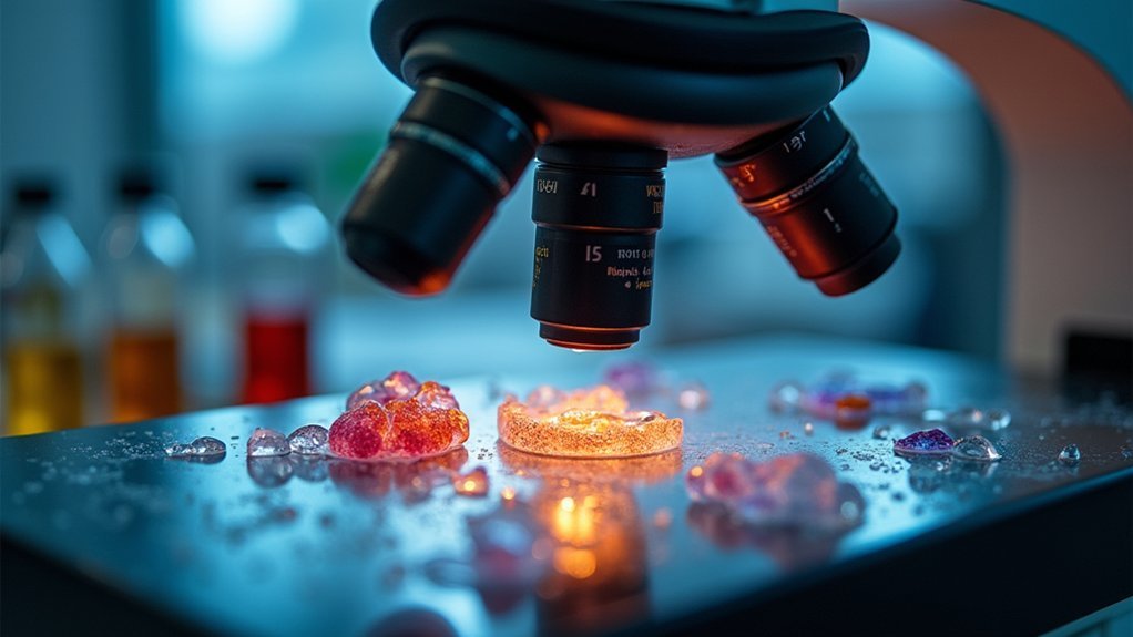
Three critical factors determine ideal light source positioning for maximum microscope resolution.
When you align your light source properly, you’ll enhance the numerical aperture of your objective lens and capture finer details in your specimens.
- Position your light ray to achieve the critical angle of incidence necessary for total internal reflection, especially when using oil immersion objectives with NA values of 1.45 or higher.
- Adjust the angle of your light source relative to the optical axis to minimize aberrations and enhance depth of field.
- Consider your specimen’s refractive index when calculating ideal positioning to maximize contrast.
- For oil immersion setups, account for the refractive properties of both the medium and objective lens to improve light collection efficiency.
Proper positioning not only brightens your images but greatly improves resolution by exploiting the full potential of your microscope’s optics.
Critical Angle Adjustments for Different Microscopy Techniques
Different microscopy applications require specific essential angle adjustments to maximize image quality and resolution.
When you’re working with water immersion objectives, you’ll need to account for the essential angle of 48.6 degrees where light traveling from water to air experiences total internal reflection.
For high-resolution imaging, oil immersion techniques utilize a slightly different essential angle of approximately 48.75 degrees, optimizing light collection efficiency.
You’ll need to adjust your setup accordingly when switching between media with different indices of refraction. This precision becomes especially vital in TIRF microscopy, where you must exceed the essential angle to generate the evanescent wave needed for surface-level fluorescence imaging.
Frequently Asked Questions
How to Calculate the Critical Angle for Light?
You’ll calculate the critical angle using Snell’s Law: sin(θ_c) = n₂/n₁, where n₁ is the refractive index of the denser medium and n₂ is the less dense medium’s index.
Is the Critical Angle Always 42?
No, the critical angle isn’t always 42 degrees. It varies depending on the refractive indices of the two media involved. You’ll calculate different values using the formula θₒ = sin⁻¹(n₂/n₁) for different materials.
What Should Be the Critical Angle for TIR?
The critical angle for TIR isn’t fixed at 42°. It depends on the two media involved. You’ll need to calculate it using sin⁻¹(n₂/n₁), where n₁ is the higher refractive index material.
What Is the Critical Angle for Light Going?
The critical angle for light going depends on the two media it travels between. You’ll need to use sin^(-1)(n₂/n₁) where n₁ is the denser medium’s refractive index and n₂ is the less dense medium’s.
In Summary
You’ve now mastered the fundamentals of critical angle calculations for microscope lighting. By applying these ten techniques, you’ll enhance image contrast and resolution across various microscopy methods. Remember that ideal illumination isn’t just about brightness—it’s about precise angular control. Keep experimenting with these calculations as you work, and you’ll consistently produce clearer, more detailed microscopic images in your laboratory work.

Leave a Reply