C-mount threads may refuse to align due to manufacturing tolerances, thread pitch variations (despite the standard 32 TPI), or backfocus issues. Even tiny 0.1mm deviations can greatly impact image quality in your optical system. Temperature changes, accumulated dirt, or previous cross-threading damage might also prevent proper mating between components. Using precision tools, thread gauges, or adjustable adapters can help you overcome these frustrating alignment challenges. Let’s explore these issues and their practical solutions in detail.
Understanding C-Mount Thread Specifications
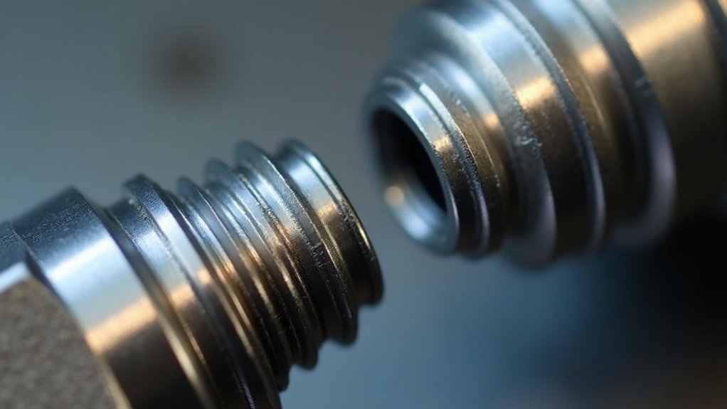
Precision is paramount when working with C-mount threads. The standardized specifications—1 inch (25.4mm) diameter with 32 threads per inch—create a foundation for compatibility across imaging systems, but they’re also where alignment issues often begin.
Precision in C-mount systems requires exacting attention to standardized specifications, where compatibility and alignment challenges converge.
When you connect components, the flange focal distance of 17.526mm becomes critical. Even minor deviations from this measurement can prevent proper focus. Your C-mount adapter may introduce additional misalignment due to manufacturing tolerances that fall within acceptable ranges individually but compound when assembled.
Pay careful attention to the rear flange interface, as this junction is particularly susceptible to alignment issues. Set screws and other locking mechanisms on some lenses require precise adjustment to maintain correct positioning.
Remember that rotational limitations in certain configurations can further restrict your ability to achieve perfect alignment in your imaging train.
Common Misalignment Causes in Optical Systems
Although C-mount threads provide standardization across imaging equipment, they introduce several common alignment challenges you’ll need to overcome.
When you tighten screws in your mount adapter, components often rotate slightly, creating misalignment in your imaging train. This rotation can position prisms and guide cameras at awkward angles, making it difficult to find guide stars.
The critical issue is that even minor misalignments—as small as 0.1mm—can severely impact image quality, especially in fast optical systems where precise backfocus is essential.
Systems with limited rotational capabilities, like Orion Thin OAGs, compound these problems by restricting your ability to properly align the prism. These design limitations explain why you’ll frequently struggle with components that refuse to align properly despite meeting thread specifications.
Manufacturing Tolerances and Their Impact

When you’re troubleshooting C-mount thread alignment issues, tolerance stack-up effects often create compounding misalignments as multiple components with slight variations interact.
Thread pitch variations, even deviations as small as 0.1mm from the standard 32 TPI specification, can prevent proper seating and create optical misalignment in your imaging system.
Different materials respond uniquely to temperature changes, causing expansion differences that further complicate precise alignment, especially in environments with fluctuating temperatures.
Tolerance Stack-Up Effects
The manufacturing process of C-mount threads inherently introduces variability that can considerably impact system performance.
When you connect multiple C-Mount components together, you’re facing what engineers call tolerance stack-up—where each component’s minor deviations combine into a significant alignment problem.
Your imaging system might include a camera, OAG, adapters, and lens—each with manufacturing tolerances of ±0.1mm. These variations don’t simply add up; they compound. The result? Components that should theoretically mate perfectly often don’t align properly in practice.
This misalignment becomes particularly problematic with devices like off-axis guiders, which already have rotational limitations.
As you add more components to your optical train, the tolerance stack-up effect intensifies, making it increasingly difficult to achieve the precise alignment needed for ideal image quality.
Thread Pitch Variations
Manufacturing tolerances affecting C-mount thread pitch create one of the most insidious problems you’ll encounter in precision optical systems.
When a standard C-mount thread (1-inch diameter, 32 TPI) deviates by even 0.1mm from specification, your components won’t properly align.
You’ll notice these variations when an adapter that worked perfectly with one lens suddenly refuses to mate correctly with another. This isn’t just an annoyance—it directly impacts your optical performance.
Thread pitch inconsistencies force components into misalignment, creating focus problems and image degradation.
The machining process inherently introduces these variations through wear and production errors, affecting thread depths and overall fit.
When selecting a C-mount adapter, you need to take into account these potential discrepancies, as they determine whether your components will form the precise optical chain your application requires.
Material Expansion Differences
Different materials used in C-mount components create another dimension of alignment challenges because they expand and contract at varying rates with temperature fluctuations.
When you’re using a c-mount lens with a nose piece made of aluminum connected to a brass adapter, their different thermal expansion coefficients can cause misalignment as your equipment heats up.
This becomes particularly problematic when you’re stacking two adapters together. A temperature change of just a few degrees can create microscopic shifts that compound the already tight manufacturing tolerances of 0.01mm.
Your imaging performance will suffer as these small discrepancies accumulate along the optical path. Even when components appear to thread together perfectly at room temperature, they may bind or loosen as materials respond differently to environmental conditions.
Thread Pitch Variations Among Manufacturers
While C-mount threads follow a standardized specification of 1-inch diameter with 32 threads per inch (TPI), significant variations exist among manufacturers that can cause frustrating alignment issues in optical systems.
These subtle differences in thread pitch might be able to pass quality control at the factory but create headaches when you’re assembling components from different sources.
When manufacturers deviate even slightly from the standard 32 TPI specification, the result is often poor mating between adapters and optical components.
You’ll notice threads that initially engage but become increasingly difficult to turn, or connections that never quite reach proper alignment.
Before purchasing or assembling C-mount components, always verify thread pitch compatibility, especially when mixing equipment from multiple vendors.
This simple precaution can save you considerable time troubleshooting mysterious image quality issues.
The Role of Backfocus in Thread Alignment
Beyond thread pitch inconsistencies, backfocus problems represent a major source of C-mount alignment failures.
When mounting components in your imaging train, even slight backfocus variations of 0.1mm can dramatically impact image quality, especially with fast optical systems. Proper backfocus isn’t just about physical fit—it’s critical for maintaining peak performance in your entire imaging system.
- Imprecise backfocus prevents proper focusing on guide stars, compromising tracking during long exposures.
- Misalignment issues compound throughout your imaging train, affecting every downstream component.
- Fast optical systems are particularly susceptible to backfocus problems, resulting in distorted star shapes.
While C-mount systems have some tolerance for minor variations, exceeding these limits quickly leads to degraded images and guiding failures.
Ensuring correct backfocus is essential for your components to work together effectively.
Wear and Tear Effects on Threading

Even the most precisely manufactured C-mount threads deteriorate over time through regular use, creating significant alignment challenges for astrophotographers.
You’ll notice this degradation manifests as stripped or damaged threads that prevent proper component alignment during attachment.
Each time you screw and unscrew your equipment, you’re potentially deforming the threads, causing misalignment issues that directly impact your optical performance.
Every threading action risks subtle deformation, leading to optical alignment issues that compromise your imaging results.
This problem compounds when dirt and debris accumulate in the threading, creating additional friction that further obstructs proper attachment.
Manufacturing tolerance variations between different C-mount components worsen these issues, as you may encounter inconsistent thread fits that frustrate your alignment efforts.
The gradual material degradation of your C-mount adapters also compromises threading integrity, making misalignment increasingly likely with continued use.
Regular inspection and gentle handling can help extend your equipment’s functional lifespan.
Tools for Proper Thread Engagement
When mounting C-mount lenses, you’ll need to confirm thread pitch compatibility between your adapter and lens to prevent cross-threading and misalignment.
You can employ specialized rotational locking techniques using precision tools like fine-tipped screwdrivers or adjustment pins to achieve proper thread engagement without damaging the components.
Investing in a thread gauge and proper alignment tools will save you significant frustration while ensuring your lens sits at the correct distance from the sensor for ideal image quality.
Thread Pitch Compatibility
Since C-mount threads follow a standard pitch of 1/2 inch with 20 TPI, ensuring proper thread compatibility between components is essential for preventing alignment issues.
When you’re working with different manufacturers’ components, even slight variations in threading can lead to frustrating misalignments and potential cross-threading damage.
- Use thread gauges to verify the exact pitch of your components before attempting to connect them.
- Apply a thin layer of appropriate lubricant to facilitate smoother engagement and reduce the risk of thread binding.
- Consider investing in adjustable C-mount adapters that can compensate for minor misalignments without compromising connection integrity.
Before forcing components together, always inspect both male and female threads for damage or contamination that might prevent proper alignment.
Remember that cross-threaded connections can permanently damage expensive optical equipment.
Rotational Locking Techniques
Thread compatibility alone won’t guarantee stable optical alignments. When your C-mount components refuse to align properly, implementing effective rotational locking methods can solve persistent misalignment issues.
Consider using locking rings or set screws to secure components in place, preventing unwanted rotation that compromises image quality. For precise adjustments, dovetail connections offer both fine-tuning capability and secure locking, maintaining alignment integrity throughout your imaging sessions.
Adjustable camera adapters allow you to optimize lens orientation without affecting critical backfocus distances. You’ll find that rotatable components markedly simplify alignment adjustments, eliminating the need to reconfigure your entire setup.
For minor orientation corrections, strategic placement of shims can achieve proper thread alignment without disrupting backfocus requirements—a practical solution when other methods aren’t feasible.
Adapter Solutions for Misaligned Components
Although C-mount threads provide standardized connections for astronomical imaging equipment, they often create alignment challenges that can’t be resolved through standard mounting alone.
Fortunately, several adapter solutions can help you overcome these frustrating alignment issues without sacrificing backfocus or image quality.
- Rotatable OAG rings allow you to adjust alignment while maintaining proper backfocus—simply loosen, rotate to the desired position, and lock in place.
- Adjustable camera adapters with dovetail connections provide flexibility to fine-tune component positioning beyond what fixed threads permit.
- Integrated systems combining camera, filter wheel, and OAG eliminate multiple connection points where misalignment can occur.
When standard solutions aren’t enough, consider using shims to make precise adjustments while keeping backfocus requirements in mind.
These practical modifications can transform a frustrating imaging setup into a properly aligned system.
Temperature Effects on Metal Threading
While adapters can solve many alignment challenges, they can’t always account for the subtle yet considerable impacts of temperature on your imaging setup.
Metal C-mount threads expand and contract as temperatures change, with even a 1°C increase causing 0.01% to 0.02% expansion—enough to affect precision connections.
This problem intensifies when your system uses different metals that expand at varying rates. As temperatures fluctuate throughout operation, these differential expansion rates can progressively worsen alignment issues.
Over time, thermal cycling accelerates mechanical wear on threads, deteriorating their fit and reliability.
To minimize these effects, allow your equipment to acclimate to ambient temperature before use. This simple thermal management practice can considerably reduce alignment problems caused by temperature-induced dimensional changes in your C-mount threading components.
Cross-Threading Damage Prevention
Despite your best efforts to align components properly, cross-threading remains one of the most common and destructive issues affecting C-mount connections.
You’ll save yourself significant trouble by adopting preventative measures before connecting any components. First, always guarantee threads are clean and free of debris that might interfere with proper alignment.
When attaching adapters or lenses, apply these proven techniques:
- Gently rotate components with minimal pressure until you feel the threads catch correctly
- Stop immediately if you encounter resistance—forcing misaligned threads will damage both parts
- Maintain a regular inspection schedule for your threads to identify wear before it causes problems
Remember that proper thread alignment starts with patience. Taking an extra moment to find the correct starting position prevents costly equipment damage and frustrating downtime.
Rotational Limitations in Imaging Trains
When building complex imaging trains, you’ll quickly discover that C-mount threading creates unique rotational challenges that can undermine system performance.
As you tighten components, screw threads can inadvertently rotate elements, misaligning your carefully planned setup.
Off-Axis Guiders present particularly frustrating obstacles due to their inherent rotational limitations.
You might find your guide camera sitting at awkward angles relative to the prism, making it nearly impossible to locate suitable guide stars.
This problem intensifies in tight configurations like Lodestar and Starlight Express OAGs, where backfocus constraints leave little room for adjustment.
To overcome these limitations, consider incorporating adjustable camera adapters and rotatable rings into your imaging train.
These solutions allow proper component orientation without compromising the critical backfocus needed for sharp imaging results.
Custom Modifications for Optimal Alignment
You’ll find that custom modifications offer practical solutions when standard C-mount adapters don’t align properly in your imaging train.
DIY alignment solutions can include adding precision-machined shims, creating rotatable interface rings, or designing flange-to-thread modifications that correct specific orientation issues.
These customizations help you maintain ideal backfocus while achieving the exact camera rotation needed for your astrophotography setup.
DIY Alignment Solutions
Although commercial solutions exist for C-mount alignment issues, crafting your own custom modifications often provides more precise control and cost-effective results.
You can create custom spacing systems using rotatable rings to maintain alignment without increasing backfocus—critical for preserving image quality while solving orientation problems.
When facing stubborn misalignments, consider these practical approaches:
- Use precision shims strategically between components, always keeping backfocus tolerances in mind to prevent degrading your guiding performance.
- Modify existing dovetail connections to create more adjustment flexibility, allowing fine positioning adjustments during setup.
- Create your own rotatable adapter system using commonly available materials that allow you to maintain proper camera orientation while preserving the critical optical path length.
Flange-to-Thread Modifications
Advanced alignment issues often require more targeted interventions than general DIY solutions. When facing persistent C-mount alignment problems, consider modifying the flange-to-thread distance to correct the relationship between lens and sensor.
You’ll find custom adapters particularly effective when you need to reorient the lens mount for proper alignment with your imaging train. Incorporating shims provides a quick fix without compromising backfocus—simply insert them at strategic points to achieve ideal positioning.
Many photographers have successfully employed adjustable camera adapters to fine-tune C-mount lens alignment during setup. For maximum flexibility, look for modifications featuring dovetail connections, which allow precise positioning adjustments.
These targeted modifications let you overcome manufacturing inconsistencies and achieve perfect alignment, ensuring your optical system performs at its full potential.
Frequently Asked Questions
What Is the Thread Standard for C-Mount?
C-mount threads follow the ANSI standard with a 1-inch diameter and 32 threads per inch. You’ll find they’re designed for a 17.526 mm flange focal distance to guarantee proper focus in your imaging system.
What Is the Difference Between C and CS Thread?
C and CS threads both use 1-inch diameter with 32 TPI pitch, but they differ in flange focal distance: C-mount is 17.526mm while CS-mount is shorter at 12.5mm. You’ll need adapters when mixing them.
What Is the Focus Distance of the C-Mount?
The C-mount focus distance is 17.5mm from the rear flange to the sensor plane. You’ll need this precise measurement to achieve proper focus, especially when adapting these lenses to different camera systems.
What Is the Distance Between Sensor and C-Mount?
The distance between your sensor and C-mount lens should be exactly 17.526 mm. This is the standard flange focal distance for C-mount systems. It’s critical you maintain this precise measurement for ideal focus performance.
In Summary
C-mount thread alignment issues aren’t just frustrating—they’re rooted in manufacturing tolerances, pitch variations, and temperature effects. You’ll need to account for these factors when building your optical system. Don’t force misaligned components; instead, check specifications carefully, avoid cross-threading, and consider custom spacers when needed. With attention to these details, you’ll achieve proper alignment and ideal imaging results despite the inherent limitations.



Leave a Reply