To install a DIY sensor cooling upgrade for your camera, first select a thermoelectric cooler compatible with your device’s specifications. Gather tools like screwdrivers and thermal paste before disconnecting power. Apply thermal paste evenly between the sensor and cooling element, then mount the Peltier module securely to the camera body. Set up the heat dissipation system, connect the power supply and temperature controller, and test thoroughly. The following steps will transform your long exposure capabilities with appreciably reduced noise.
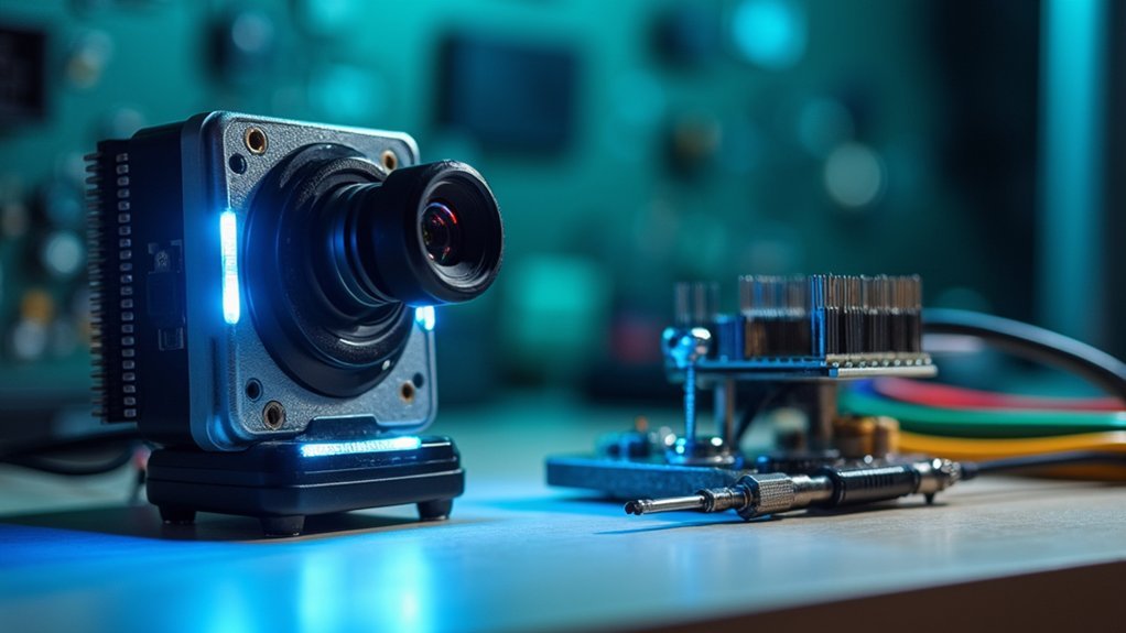
Selecting the Right Cooling System for Your Microscope Camera
When initiating a cooling system upgrade for your microscope camera, you’ll need to carefully match the system’s capabilities to your specific needs.
Calculate your camera’s heat output first, ensuring the cooling system can handle extended imaging sessions without performance degradation.
Before any purchase, calculate your camera’s heat output to ensure your cooling system will sustain peak performance during long imaging sessions.
Look for solutions that incorporate thermoelectric coolers (TECs) utilizing the Peltier effect for efficient temperature regulation.
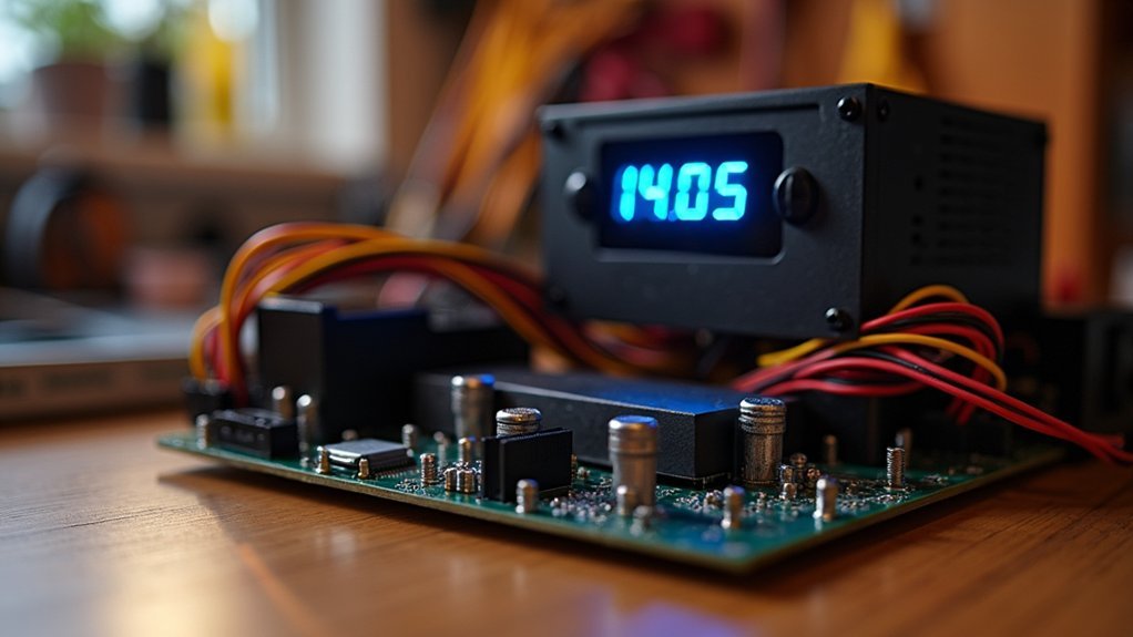
Your system should include a reliable coolant temperature sensor and thorough temperature monitoring features, allowing you to adjust settings based on your experimental conditions.
Don’t overlook physical compatibility—check mounting options and dimensions before purchasing.
Finally, consider the system’s operational noise level, as quieter cooling units prevent interference with sensitive microscopy work and create a more pleasant laboratory environment.
Required Tools and Materials for Sensor Cooling Installation
You’ll need a thorough socket and ratchet set to properly install your sensor cooling system, along with protective gear like gloves and eye protection to handle coolant safely.
Don’t forget to secure a drain pan to capture any spilled coolant during the installation process, preventing messy accidents in your workspace.
Specialty mounting components, including appropriate electrical connectors and replacement coolant, will guarantee your cooling upgrade functions properly after installation.
Essential Installation Gear
Proper preparation with the right tools and materials makes a sensor cooling upgrade considerably smoother and safer. Before tackling temperature sensors, gather these essential installation gear items to guarantee a successful DIY project.
| Tool/Material | Purpose |
|---|---|
| Socket & ratchet set | Removing and installing sensor |
| Flathead screwdriver | Disconnecting electrical components |
| Drain pan | Catching coolant spillage |
| Safety gloves & eye protection | Personal protection |
| Torque wrench | Proper tightening to specs |
Don’t forget to have your replacement coolant temperature sensor and fresh coolant ready. Thread sealant may also be necessary depending on your vehicle’s specifications. Using the proper tools not only makes the job easier but helps prevent damage to components and assures a leak-free installation.
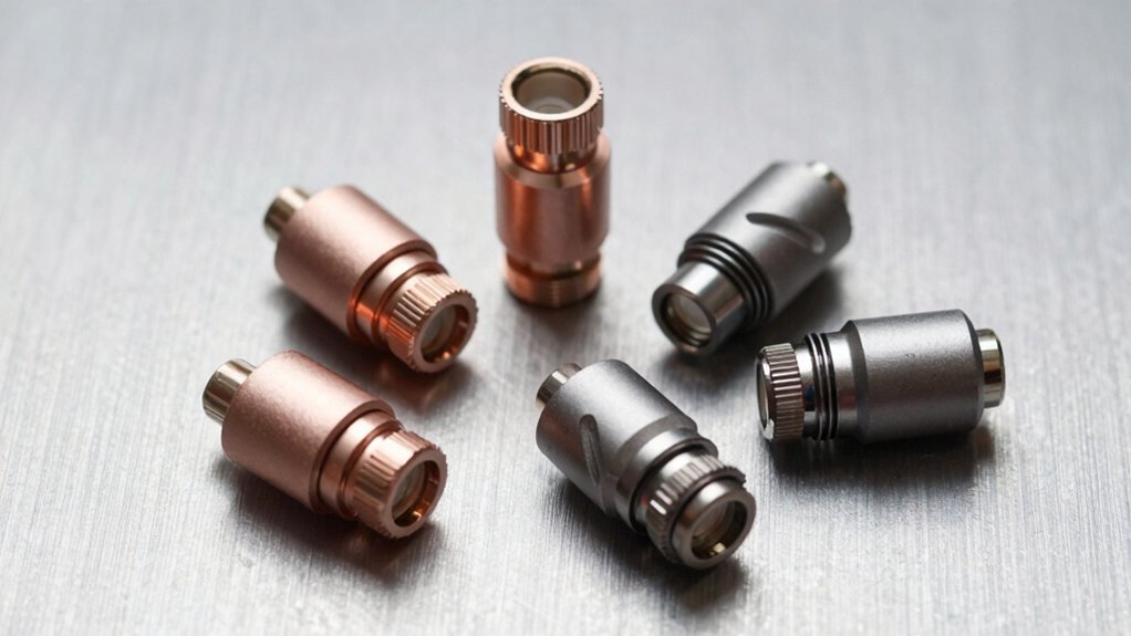
Specialty Mounting Components
Beyond standard tools, specialty mounting components play a critical role in sensor cooling installations, ensuring both functionality and longevity. When upgrading your cooling system, you’ll need specific hardware to achieve accurate temperature readings and prevent leaks.
- Threaded bungs provide secure sensor placement, ensuring the bulb remains properly immersed in coolant—critical for capturing precise temperature readings in real-time.
- Radiator hose adapters offer an alternative mounting solution, allowing you to install sensors directly in the upper hose where hot coolant flows.
- Insulated clamps prevent heat transmission to your sensors, maintaining reading accuracy and extending sensor life.
Don’t forget to apply thread sealant to sensor threads when required.
These specialty mounting components might seem minor, but they’re essential for creating a professional-grade sensor cooling system that performs reliably under all conditions.
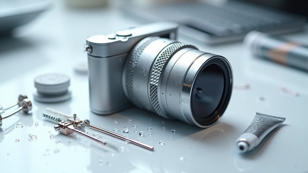
Preparing Your Microscope Camera for the Cooling Upgrade
Five essential preparations will guarantee your microscope camera is ready for a cooling upgrade.
First, verify your camera’s compatibility with cooling systems by reviewing the manufacturer’s specifications for temperature regulation and sensor cooling options.
Next, gather all required tools including socket sets and screwdrivers before you begin.
Preparation prevents frustration—assemble your socket sets and screwdrivers before touching a single component of your microscope camera.
Then, safely disconnect your camera from power sources and remove it from the microscope mount to prevent accidental damage during installation.
Fourth, inspect all cooling components—especially the temperature sensor and cooling unit—confirming they match your camera’s specifications and are in proper working condition.
Finally, thoroughly read the installation instructions specific to your camera model to ascertain you’ll correctly integrate the cooling system with your existing hardware and software configuration.
Installing the Thermal Interface Between Sensor and Cooling Element
You’ll need to apply a thin, even layer of thermal paste to guarantee proper heat transfer between your imaging sensor and the cooling element.
To verify good contact quality, check for consistent paste distribution when you separate the components after a test fitting, looking for complete coverage without air pockets.
Test thermal conductivity by monitoring temperature readings during short operational periods, confirming that heat efficiently moves away from the sensor.
Paste Application Methods
Applying thermal paste correctly forms the critical foundation of your sensor cooling upgrade. Before you begin sensor installation, clean both surfaces thoroughly to remove any residue that could compromise thermal conductivity.
Apply a pea-sized amount of paste to the center of your sensor—this is typically sufficient for even coverage without risking overflow.
For effective application, consider these techniques:
- The “dot method” – Place a small dollop in the center and let pressure distribute it
- The “X method” – Create an X-pattern for larger sensors requiring more coverage
- The “spread method” – Use a plastic card to manually distribute a thin layer
Once applied, allow the paste to cure according to manufacturer specifications before operating your system at full capacity.
Regular inspection during maintenance will guarantee continued peak performance.
Testing Contact Quality
Proper contact between your sensor and cooling element represents the most critical factor in achieving ideal thermal performance. After applying your TIM, you’ll need to verify that contact is uniform and effective.
| Test Method | Good Contact | Poor Contact |
|---|---|---|
| Temperature readings | Stable, consistent values | Erratic, unexpectedly high readings |
| Thermal imaging | Even heat distribution | Hot spots or uneven patterns |
| Stress testing | Predictable temperature curves | Sudden spikes or fluctuations |
Monitor your sensors for 10-15 minutes after installation. If you notice inconsistent temperature readings, you’ll need to disassemble and reapply the TIM. Remember, even high-quality thermal paste can’t compensate for improper application. Air gaps between surfaces create significant thermal resistance, reducing cooling efficiency. If readings remain unstable after reapplication, check for warping or damage on contact surfaces.
Mounting the Peltier Cooling Module to the Camera Body
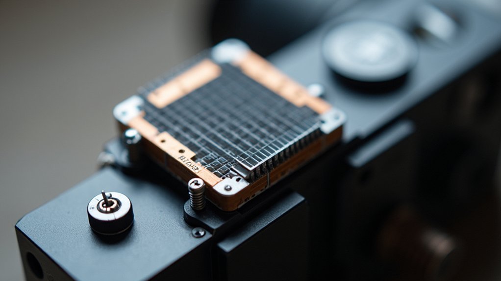
The foundation of an effective DIY sensor cooling system lies in properly mounting the Peltier module to your camera body. Secure attachment creates the best thermal contact needed for efficient heat transfer.
Position the cold side against your camera while directing the hot side toward a heat sink or ventilated area for proper heat dissipation.
- Apply thermal adhesive or use screws to firmly attach the Peltier module, ensuring no air gaps that would reduce cooling efficiency.
- Connect to a compatible 12V power source that meets your module’s specific voltage and current requirements.
- Install a temperature sensor near the camera body to monitor conditions and make real-time adjustments during extended shooting sessions.
Don’t forget to insulate around the module to prevent environmental heat from compromising your cooling setup’s performance.
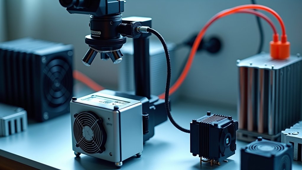
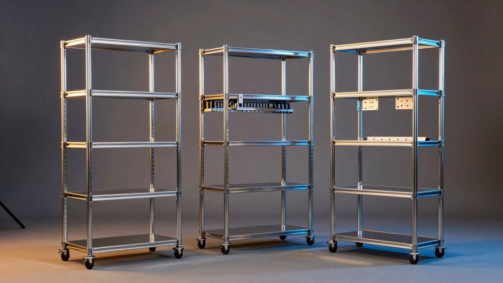
Setting Up the Heat Dissipation System and Radiator
With your Peltier module securely mounted, you’ll now need an efficient heat dissipation system to manage the thermal output. Position your coolant temperature sensor where it receives consistent flow—ideally near the thermostat housing or in the hot side of the radiator. This guarantees your cooling system operates with accurate temperature readings.
| Component | Ideal Location | Common Mistake |
|---|---|---|
| Temp Sensor | Hot side radiator | Stagnant areas |
| Radiator | End tanks with ports | Core mounting |
| Fan | Secured to frame | Attached to core |
| Tee Fittings | Heater supply hose | Variable flow areas |
| Coolant Lines | Direct routing | Kinked pathways |
When mounting fans, attach them to the steel frame rather than the radiator core to prevent damage. Your sensor would perform best when fully immersed in flowing coolant, avoiding areas where heater control valves might create inconsistent readings.
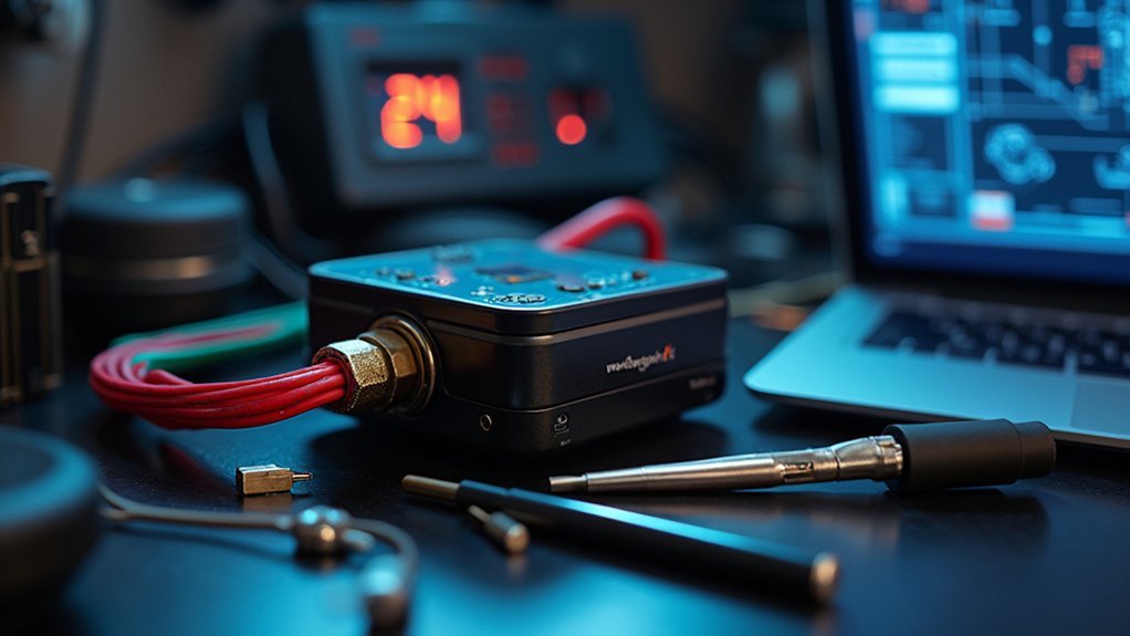
Connecting the Power Supply and Temperature Controller
Connecting your power supply and temperature controller correctly forms the backbone of an effective sensor cooling system. Before installation, check that your electric fan controller requires either 12V or 24V DC input—using incompatible voltage will damage components.
Follow these critical steps:
- Wire the power supply to your temperature controller using the provided diagram, carefully matching positive and negative terminals while using appropriate gauge wiring for your current requirements.
- Connect the temp sensor to the designated input terminals, ensuring it’s properly positioned to measure your target location accurately.
- Attach controller outputs to cooling system components like fans and pumps, securing all connections to prevent shorts.
After wiring is complete, power on the system and verify the controller responds properly to temperature changes before finalizing your installation.
Testing and Calibrating Your New Cooling System
Proper testing and calibration represent two critical steps that guarantee your DIY sensor cooling system performs reliably.
After installation, start your engine and let it idle for several minutes to verify the coolant reaches operating temperature, allowing your new temperature sensor to provide accurate readings.
Always verify sensor accuracy by allowing your engine to reach full operating temperature during initial testing.
Take your system for a test drive while monitoring the temperature gauge to confirm the sensor correctly reflects engine temperature under load.
Inspect the installation site for any coolant leaks that could compromise readings and potentially cause overheating.
Use a multimeter to test your sensor’s resistance at different temperatures, comparing results against manufacturer specifications.
Review temperature data regularly to confirm consistent performance, and adjust fan activation settings based on sensor readings to maintain peak cooling efficiency.
Optimizing Long Exposure Performance With Cooled Sensors
Now that your cooling system is properly tested and calibrated, let’s focus on maximizing sensor performance during long exposure conditions.
Your sensor’s placement is vital for consistent temperature readings. You’ll need to guarantee the sensor maintains direct contact with the coolant flow at all times.
- Install the sensor bulb in either the upper radiator hose or a dedicated bung in the radiator where coolant actively circulates.
- Secure with insulated clamps to shield the sensor from external heat influences that could compromise accuracy.
- Create proper airflow around the installation area to prevent heat buildup that leads to false readings.
Remember to regularly inspect your sensor’s immersion and connections.
Even minor positioning issues can considerably impact your cooling system’s reliability during those essential long-exposure photography sessions.
Frequently Asked Questions
Can You Replace a Coolant Sensor Yourself?
Yes, you can replace a coolant temperature sensor yourself with basic tools. It’s a straightforward DIY job involving disconnecting the electrical connector, unscrewing the old sensor, and installing the new one with proper sealant.
Where and How Should Temperature Sensors Be Mounted?
You’ll want to mount temperature sensors near the thermostat housing or in the upper radiator hose where they’re immersed in flowing, hot coolant. Avoid stagnant areas like drain ports for accurate, lag-free readings.
How to Install Temperature Sensors?
To install temperature sensors, place them in areas with consistent coolant flow near the thermostat housing or upper radiator hose. You’ll need to drill and tap into suitable components or use existing ports for mounting.
What Is the Best Height for a Temperature Sensor?
Mount your temperature sensor at or slightly above the upper radiator hose level, which captures the hottest coolant temperatures accurately. Don’t place it too low where coolant stratification might affect readings.
In Summary
You’ve now transformed your microscope camera with professional-grade cooling! With reduced thermal noise, you’ll capture clearer images during those long exposures. Remember to monitor your temperature settings regularly and keep the cooling system dust-free. Don’t hesitate to fine-tune your setup as you gain experience. Your DIY upgrade rivals commercial solutions at a fraction of the cost—enjoy the stellar results of your hard work!
Leave a Reply