Image drift occurs due to thermal expansion, mechanical vibrations, poor alignments, and electrostatic forces affecting your equipment. To stop it, secure all components, maintain stable temperature, use vibration isolation platforms, and implement proper guiding systems. For microscopy, allow thermal equilibration and apply conductive coatings where appropriate. Software solutions can provide real-time drift compensation with sub-pixel precision. The right combination of environmental control and technical adjustments will dramatically improve your imaging stability.
What Causes Image Drift And How To Stop

When capturing deep-sky images over extended periods, image drift can frustrate even the most experienced astrophotographers. This common problem often stems from differential flexure between your guide scope and main telescope, causing them to gradually misalign during imaging sessions.
Poor polar alignment is another major culprit, resulting in field rotation that manifests as drift. You’ll need to perform accurate initial setup and regular alignment checks throughout your session.
Mechanical issues like mirror flop in SCTs or loose components can worsen image drift, so verify all connections are secure.
Don’t overlook environmental factors—temperature changes and vibrations from nearby equipment contribute considerably to drift problems.
For a more permanent solution, consider switching to Off-Axis Guiding (OAG), which greatly reduces drift by eliminating differential flexure compared to traditional guide scopes.
Understanding Image Drift in Microscopy
Image drift in microscopy stems from thermal expansion of materials, often occurring when your chamber experiences temperature fluctuations during imaging.
You’ll notice mechanical stability issues manifesting as unwanted sample movement, particularly when components aren’t properly secured or calibrated.
Environmental vibrations from nearby equipment, building systems, or even foot traffic can greatly impact your imaging quality, making vibration isolation systems essential for high-resolution microscopy work.
Thermal Expansion Effects
Despite advanced technology in microscopy, thermal expansion remains a significant challenge for obtaining stable, high-resolution images. When temperature fluctuates within your SEM chamber, materials expand and contract, causing unwanted movement of both samples and electron beams.
This thermal instability directly contributes to image drift, undermining the quality of your observations.
To minimize thermal expansion-induced image drift:
- Maintain stable temperature conditions within your microscope chamber
- Monitor environmental parameters consistently during imaging sessions
- Guarantee proper sealing of your SEM chamber to prevent external fluctuations
- Invest in environmental control systems for better stability
- Allow sufficient time for thermal equilibrium before beginning sensitive imaging work
Mechanical Stability Issues
Although thermal expansion greatly contributes to image drift, mechanical stability issues represent an equally critical challenge in microscopy systems.
Your imaging results can degrade markedly when external vibrations from nearby equipment or foot traffic disrupt your sample or electron beam position during observation.
Electrostatic forces between charged components further complicate matters, especially in sensitive setups like SEM.
You’ll notice these mechanical stability issues manifest as unwanted shifts in your field of view, compromising image quality and measurement accuracy.
To combat these problems, you should implement vibration isolation platforms and maintain consistent environmental conditions.
Don’t overlook the importance of regular calibration and alignment of your microscope components—these maintenance procedures are essential for minimizing drift and ensuring ideal imaging performance throughout your research activities.
Environmental Vibration Control
When conducting precision microscopy work, you’ll encounter environmental vibrations as one of the most pervasive yet manageable causes of image drift.
These subtle disturbances can compromise your imaging quality by inducing unwanted movement in your sample or electron beam.
- External sources like foot traffic and nearby machinery introduce mechanical vibrations that destabilize your microscope setup.
- Vibration isolation platforms and specialized damping systems effectively minimize these disturbances.
- Maintaining stable temperature and humidity within the SEM chamber prevents thermal expansion-induced drift.
- Regular environmental monitoring helps identify and address potential vibration sources proactively.
- Even seemingly minor vibrations can accumulate over time, notably affecting high-resolution imaging results.
Thermal Expansion Effects on Sample Stability
You’ll notice that materials with different expansion rates can cause uneven movement within your sample during temperature changes.
Heat gradients form when parts of your microscopy system warm at different rates, creating directional drift that’s difficult to predict.
The microscope stage itself may warp slightly under thermal stress, shifting your sample’s position and compromising image stability.
Material Expansion Rate Differences
Despite careful instrument calibration, thermal expansion remains one of the most challenging factors affecting image stability in microscopy.
When you’re working with samples composed of different materials, their varying expansion rates can sabotage your imaging quality.
- Metals expand considerably more than ceramics when heated, creating stress at material interfaces.
- Even minor temperature fluctuations (just a few degrees) can cause noticeable sample drift.
- Multi-material structures are particularly vulnerable to misalignment during imaging.
- Material expansion rate differences can introduce progressive distortion as scanning continues.
- Samples with heterogeneous composition may develop internal stresses that alter surface morphology.
Understanding these thermal expansion dynamics is essential for anticipating drift patterns.
You’ll need to account for these material-specific behaviors when designing your experimental setup, especially for high-resolution imaging where nanometer-scale movements can completely compromise your results.
Heat Gradient Formation
Temperature variations within the SEM chamber create problematic heat gradients that greatly impact your imaging quality.
When these thermal differentials develop, they trigger uneven expansion of both your sample and the microscope components, causing positional shifts that manifest as drift during observation.
You’ll notice this effect most prominently during high-magnification work, where even microscopic movement greatly alters image scale and resolution.
The chamber environment must remain thermally stable to prevent these disruptive gradients. Guarantee proper sealing of your SEM chamber to maintain consistent conditions and minimize external influences.
Monitor and control temperature and humidity levels regularly, as fluctuations in these parameters accelerate drift problems.
Microscopy Stage Warping
While managing chamber conditions prevents many drift issues, the microscopy stage itself represents a major source of thermal instability. When temperature fluctuations occur, even minimal changes can trigger microscopic warping of your stage components, causing your samples to drift during imaging.
- Different materials in your stage expand at varying rates, creating misalignment
- Even a 0.5°C change can cause sample positions to shift by several microns
- Metal components typically expand more rapidly than glass or ceramic parts
- The sample itself may warp differently than its mounting medium
- Expansion effects compound over time, gradually worsening drift during extended imaging sessions
To minimize these effects, you’ll need temperature-stabilized environments, materials with matching thermal expansion coefficients, and regular calibration routines that account for any residual drift.
Mechanical Vibration Sources and Isolation
When capturing precise images, even the slightest mechanical vibrations can destroy hours of careful work. These disturbances often originate from external sources like foot traffic, nearby equipment, or environmental factors that cause unwanted movement in your imaging system.
To combat this issue, place your setup in a low-vibration area away from heavy machinery and high-traffic zones. Invest in vibration isolation platforms specifically designed for sensitive equipment—they’ll greatly reduce external vibration impacts on imaging stability.
Don’t forget to secure all equipment and regularly assess your surroundings for potential vibration sources. This proactive approach helps you identify and mitigate disturbances before they affect your imaging process.
Electrostatic Forces and Their Influence on Drift
Beyond mechanical vibrations, another invisible force can sabotage your imaging quality: electrostatic interactions. These charges can greatly impact image drift by creating unwanted movement of samples or electron beams during observation.
- Charged components in your imaging system attract or repel samples, causing position fluctuations.
- Electron beam interaction with samples generates electrostatic charges that destabilize imaging.
- Sample charging effects worsen in non-conductive materials, intensifying drift problems.
- Applying conductive coatings during sample preparation minimizes charging-related drift.
- Maintaining proper vacuum levels prevents gas molecule interactions that amplify electrostatic effects.
You’ll see immediate improvement in stability when you address these electrostatic issues.
Proper Sample Preparation Techniques
Although researchers often focus on equipment settings to combat image drift, proper sample preparation forms the foundation of stable, high-quality imaging.
You’ll need to secure your sample firmly to minimize movement and vibrations that contribute to drift during the imaging process.
Consider applying conductive coatings to reduce charging effects that create electrostatic forces and destabilize imaging conditions.
You should also maintain strict temperature and humidity control during sample preparation to prevent thermal expansion that causes drift.
Before placing your sample in the SEM chamber, verify you’ve established ideal high vacuum conditions. This minimizes gas interactions that lead to unwanted specimen movement.
While imaging, continuously monitor and calibrate your equipment to detect any drift in real-time, allowing for immediate corrections.
Environmental Control Strategies
Since temperature fluctuations directly affect sample expansion and contraction, maintaining precise environmental conditions is critical for minimizing image drift. Your SEM’s imaging quality depends heavily on a stable environment within and around the instrument.
Temperature stability isn’t optional—it’s fundamental to preventing drift and preserving the integrity of your microscopy data.
- Install dedicated environmental control systems to regulate temperature and humidity in your imaging facility.
- Monitor environmental parameters continuously through automated sensors to detect problematic fluctuations early.
- Guarantee proper chamber sealing to maintain vacuum integrity and prevent unwanted gas interactions.
- Implement vibration isolation platforms to shield your microscope from external mechanical disturbances.
- Consider a specialized enclosure for your SEM that provides an additional barrier against environmental variations.
These measures will considerably reduce environmentally-induced drift, allowing you to capture crisp, stable images even during extended acquisition sessions.
Advanced Mounting and Fixation Methods
Advanced mounting systems like vibration isolation platforms effectively shield your setup from external disturbances that cause image drift.
Precision bracket assemblies, particularly those utilizing bracing plates, can connect dual rigs with enhanced stability to minimize equipment flexure.
You’ll find magnetic mounting solutions offer both secure fixation and convenient adjustment capabilities when fine-tuning your imaging configuration.
Vibration Isolation Platforms
When external vibrations disrupt your imaging process, vibration isolation platforms serve as your first line of defense. These specialized systems absorb and dampen mechanical disturbances that would otherwise compromise your image quality.
- Air-filled chambers and rubber components actively absorb vibrations before they reach your equipment.
- Properly installed platforms can dramatically reduce image noise and prevent drift in SEMs and telescopes.
- Regular environmental assessment helps identify and mitigate new vibration sources like foot traffic.
- High-quality vibration isolation platforms provide a stable foundation for consistent, reliable imaging results.
- Your investment in proper vibration damping directly correlates with improved performance and precision.
Precision Bracket Assemblies
Stability serves as the cornerstone of successful imaging, and precision bracket assemblies deliver this essential foundation for your telescope and guiding systems. These rigid mounting solutions minimize flexure that would otherwise cause your images to drift during long exposures.
When selecting precision bracket assemblies, look for adjustable features that allow fine-tuning alignment between your guide scope and main telescope. This optimization reduces differential flexure—a common culprit behind tracking issues.
Choose assemblies made from high-quality materials that resist vibrations and thermal expansion. During installation, verify you tighten all connections properly to prevent unwanted movement.
Don’t forget to perform regular maintenance checks on your precision bracket assemblies. Even the best hardware can loosen over time, potentially reintroducing alignment issues and image drift that you’ve worked hard to eliminate.
Magnetic Mounting Solutions
Modern astrophotographers increasingly turn to magnetic mounting solutions as a sophisticated alternative to traditional bracket systems. These innovative mounts combat image drift through their inherent stability and precise positioning capabilities.
- Magnetic mounts minimize mechanical flexure and vibration, dramatically reducing drift-causing movement during long imaging sessions.
- Quick adjustments and repositioning can be made while maintaining perfect alignment with your optical path.
- Integrated locking mechanisms secure your equipment firmly against external disturbances.
- Versatile designs accommodate various equipment sizes and weights, ensuring compatibility with your specific setup.
- Improved cable management prevents snagging and reduces additional sources of unwanted movement.
You’ll find these magnetic systems particularly valuable when imaging under challenging conditions or when pursuing high-magnification targets that require exceptional stability throughout your imaging sequence.
Real-Time Drift Compensation Systems
As astronomical imaging sessions stretch into hours, real-time drift compensation systems become essential tools for maintaining precise target positioning.
These systems employ sophisticated algorithms that continuously monitor your imaging target and make automatic adjustments, achieving tracking precision with RMS values under 0.5 arcsec/px.
Unlike traditional guide scopes, Off-Axis Guiding (OAG) implementations eliminate differential flexure and mirror flop issues, providing considerably more stable imaging performance.
The integrated software automatically processes feedback from guiding cameras to correct both RA and DEC drift without manual intervention.
For ideal results, you’ll need to calibrate your system regularly to account for mechanical wear and environmental changes.
This maintenance guarantees your drift compensation continues to perform effectively, keeping your celestial targets centered throughout extended imaging sessions.
Software-Based Drift Correction Approaches
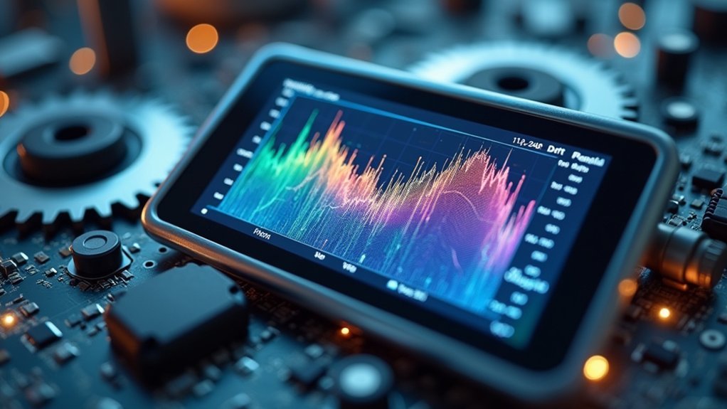
While hardware solutions tackle drift at its source, software-based drift correction approaches offer powerful alternatives that work with your existing image data. Modern astrophotography software provides sophisticated tools to combat drift effects without additional equipment.
- Real-time monitoring systems continuously adjust imaging parameters, compensating for drift during acquisition.
- Programs like MaximDL and Astro Pixel Processor offer automated guiding adjustments that track your guide star consistently.
- Post-processing stabilization tools can correct drift-induced distortions when aligning and stacking images.
- Reference frame features let you align multiple exposures based on your specific target object.
- Software can analyze tracking data to identify drift patterns and implement corrective algorithms automatically.
These software solutions give you flexibility to salvage shoots affected by drift and improve your imaging results, even when working with less-than-ideal mounting or in challenging conditions.
Optimizing Imaging Parameters to Minimize Drift
Successfully capturing drift-free astrophotography images depends greatly on how you configure your imaging parameters before starting your session.
Precise polar alignment is absolutely critical—even minor misalignments create progressive drift that becomes apparent during longer exposures.
Don’t overlook mechanical stability in your setup.
Take time to tighten all connections and components to minimize differential flexure.
If you’re using an SCT, consider implementing Off-Axis Guiding rather than a guide scope to eliminate flexure issues.
You’ll also need to account for environmental conditions.
Temperature and humidity changes can affect your equipment’s stability throughout the night.
Utilize your software’s automated features for continuous focus adjustments and calibration during acquisition to maintain ideal imaging parameters as conditions change.
Hardware Solutions for Stability Enhancement
Beyond optimizing your imaging parameters, physical hardware upgrades can substantially reduce drift in your astrophotography setup.
When examining your equipment, focus on minimizing mechanical flexure and vibration to maintain precise star tracking throughout long exposures.
- Secure all components tightly—telescope, mount, guide scope, and camera—to reduce flexure and improve stability.
- Consider upgrading to Off-Axis Guiding (OAG) instead of a guide scope, especially with SCTs, to minimize differential flexure.
- Level your mount regularly and verify all connection points remain secure to prevent sagging during imaging sessions.
- Implement proper cable management by securing all cables to prevent tugging and unwanted movement.
- Install vibration isolation platforms or position your setup away from sources of vibration to mitigate external disturbances.
Drift Measurement and Quantification Tools
Three essential tools allow astrophotographers to accurately measure and quantify image drift during imaging sessions. Your guiding software displays RMS values, with ideal performance falling between 0.48-0.68 arcseconds per pixel. Stacking programs like Astro Pixel Processor let you select reference frames to compare star positions across subframes. Drift tests using unguided exposures help isolate equipment versus polar alignment issues.
| Tool Type | Measurement Capability | Emotional Impact |
|---|---|---|
| Guiding Software | Real-time RMS values | Relief when seeing <0.5" numbers |
| Stacking Programs | Frame-to-frame alignment | Satisfaction in perfect star alignment |
| Drift Test Images | Unguided drift patterns | Frustration with poor alignment |
| Guiding Graphs | Temporal drift analysis | Excitement when seeing flat lines |
| Log Files | Historical trend data | Confidence in system stability |
Continuous monitoring during sessions guarantees you’ll catch drift issues before they ruin your data.
Frequently Asked Questions
Does Atmospheric Refraction Contribute to Image Drift During Long Exposures?
Yes, atmospheric refraction can contribute to image drift during long exposures. You’ll notice stars appear to move as light bends through different air layers with varying temperatures and densities. It’s called seeing conditions.
How Does Field Rotation Differ From Image Drift?
Field rotation occurs from Earth’s rotation causing stars to arc around the celestial pole, while image drift happens from equipment issues like poor polar alignment. You’ll notice they’re different astronomical tracking problems requiring distinct solutions.
Can Autoguiding Systems Completely Eliminate All Types of Image Drift?
No, autoguiding systems can’t completely eliminate all types of drift. While they effectively correct tracking errors, they won’t fix issues like field rotation, differential atmospheric refraction, or equipment flexure without specialized solutions.
Do Different Camera Sensors Exhibit Varying Susceptibility to Drift Issues?
Yes, your camera’s sensor type impacts drift susceptibility. CMOS sensors typically show more drift than CCD sensors. Temperature regulation affects both types, but larger sensors usually exhibit more pronounced drift patterns than smaller ones.
How Does Image Drift Affect Narrowband Versus Broadband Astrophotography?
Narrowband astrophotography suffers less from image drift than broadband because you’re capturing specific wavelengths, making alignment easier. You’ll notice drift more in broadband imaging where all visible light affects your detailed celestial targets.
In Summary
Image drift can wreak havoc on your microscopy work, but you’re now equipped to combat it. By addressing thermal effects, vibrations, and electrostatic forces, you’ll greatly improve stability. Whether you’re implementing software corrections, optimizing imaging parameters, or investing in hardware solutions, you can effectively measure and minimize drift. With these strategies, you’ll capture clearer, more reliable images for your research or analysis.

Leave a Reply